Description
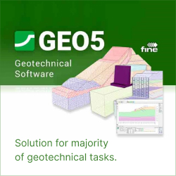
GEO5 is an intuitive software suite providing a solution for the majority of geological & geotechnical tasks. From geological site investigation, subbase model creation up to a wide range of analyses such as slope stability, deep excavation, and tunnel, GEO5 consists of a wide range of powerful programs based on analytical methods and the Finite Element Method. GEO5 is one of the most preferred software by Geologists & Geotechnical Engineers across the world.
Various Modules of GEO5 Software –
- Slope Stability – This module is used to perform slope stability analysis (embankments, earth cuts, anchored retaining structures, MSE walls, etc.). The slip surface is considered circular or polygonal and analyzed by all general methods.
- Slope Stability – Water Flow – This is an extension module for the determination of the pore pressures in the slope by using the groundwater seepage analysis.
- Sheeting Check – This program is used to make advanced design of embedded retaining walls using the method of elasto-plastic non-linear analysis. It allows the user to model the real structure behavior using stages of construction, to calculate the deformation and pressures acting upon the structure, to verify the internal anchor stability or to verify cross-sections (steel, RC, timber) and the bearing capacity of the anchors.
- Sheeting Design – This program is used to quickly design non-anchored walls and to make a basic design of anchored retaining walls (Sheet pile, Soldier pile, Diaphragm and Pile walls). The results show the required embedment lengths, the internal forces on the structure and the forces in anchors. The program provides verification of RC, steel or timber cross sections.
- Cantilever Wall – This program is used to verify cantilever retaining wall design.
It offers a number of wall shapes and analyzes reinforced concrete cross-sections. - Gravity Wall – This program is used for design of gravity retaining walls. It offers
a range of wall shapes and verifies mass concrete cross-sections.
- MSE Wall – This program is used for verification of mechanically stabilized earth walls and segmental retaining walls reinforced by geogrids (georeinforcements).
- Gabion – This program is used for gabion wall design. It allows analysis of any structure shapes including overhangs requiring anchoring.
- Masonry Wall – This program is used for design and analysis of reinforced masonry block wall according to various standards.
- Redi-Rock Wall – This program is used for designing advanced retaining walls using Redi-Rock wall system(USA). The program is identical to the RRWall+program (available on Redi-Rock webpages for free), but it also allows full communication with other GEO5 programs.
- Prefab Wall – This program is used to verify retaining walls made of prefabricated blocks (retaining block walls).
- Nailed Slope – This program is used to design soil nail walls and slopes of various shapes with shotcrete cover or steel mesh.
- Anti-Slide Pile – This program is used for design of pile walls stabilizing slope movement or increasing safety factor of the slope. The first analysis should be done in the Slope Stabilityprogram, where the active and passive forces acting on pile wall are computed. Next, the load and slip surface position are transferred to the Anti-Slide Pile program, where other analyses are performed (determination of internal forces on pile,
pile deformation and dimensioning of pile reinforcement).
- Earth Pressures – This program computes basic earth pressures (active pressure, passive pressure and pressure at rest) acting upon an arbitrary shaped structure.
- Spread Footing – This program is used for the design of spread footings (spread or strip footing) subject to general load. It computes vertical and horizontal bearing capacity, settlement and rotation of a footing, and determines required longitudinal and shear reinforcement (punching).
- Spread Footing CPT – This program is used for the design and verification of spread footing foundations based on data from field tests (CPT, SPT, PMT). The program performs an analysis for vertical and horizontal bearing capacity, settlement and longitudinal and shear reinforcement (punching).
- Pile – This program is used for analysis of vertical bearing capacity of a single pile loaded both in tension or compression, pile settlement as well as horizontal bearing capacity of a single pile.
- Micropile – This program is used for verification of steel tube micropiles. When calculating the micropile bearing capacity, the program verifies both the root and shaft.
- Pile Group – This program is used to analyze a pile group (pile raft foundation with a rigid pile cap) using both spring method (FEM), or analytical solutions. Both floating piles and piles fixed into subsoil can be considered.
- Pile CPT – This program verifies the vertical bearing capacity and settlement of piles, based on the results provided by (static) cone penetration tests (CPT) and standard penetration tests (SPT).
- Beam – This program provides the analysis of foundation beams resting on elastic foundation (subsoil).
- Slab – The program Slab is used for design of foundation mats (rafts) and slabs of any shape on elastic subsoil or piles, using the Finite Element Method.
- Settlement – This program is used to determine vertical settlement and time-dependent consolidation of soils under embankments, foundations, earth dams and surface loads (surcharges).
- Abutment – This program is used to design bridge abutments including wing walls. It allows to check the abutment for overturning, translation, bearing capacity of foundation soil and dimensioning of decisive or reinforced concrete sections (including wings).
- Rock Stability – This program is used to analyze the stability of rock slopes and walls for a specified type of failure, including a planar or polygonal slip surface or rock wedge.
- Shaft – This program is used to analyze spatial earth pressures on circular shaft and determination of internal forces on the structure.
- Ground Loss – This program is used for analysis and determination of the shape of subsidence trough above excavations and to evaluate the damage to buildings situated in the affected area.
- FEM – This program, based on the finite element method, can model
and analyze a wide range of geotechnical problems, including terrain settlement, sheet pile/diaphragm walls, slope stability, excavation analysis. It offers several material models for soils and a variety of structural elements such as walls, anchors, geotextiles
or geogrids. The GEO5 FEM is used to compute displacements, internal forces in structural elements, stresses and strains and plastic zones in the soil and other quantities in every construction stage. With extension modules the program also performs the Tunnelexcavation analysis, the steady sate or transient Water Flowanalysis, the coupled Consolidation analysis, or the dynamic impact of an Earthquake. - FEM-Tunnel – The FEM – Tunnel is used to design and analyze tunnels. It include a specialized tools for the definition of tunnel lining, system of anchors and rock bolts and grouting-strengthen regions. The relaxation factor assigned to each construction stage takes the 3D effect of the excavation into account.Tunnel is an extension module of the FEM programfor the analysis of general geotechnical problems.
- FEM-Water Flow – The FEM – Water Flow is used to perform steady state or transient water flow analysis (seepage). Given the material properties and initial conditions at the model boundaries the program computes the evolution and steady state of the pore pressure distribution, degree of saturation in the unsaturated zone, seepage velocities and inflow/outflow through the model. The resulting ground water table can be imported into the standard stress-strain analysis. Water Flow is an extension module of the FEM programfor the analysis of general geotechnical problems.
- FEM – Consolidation – The FEM – Consolidation is used to perform time dependent settlement analysis under foundations, embankments and surface loads (surcharges). Given the external load and the mechanical and hydraulic boundary conditions the coupled analysis provides the evolution of displacements, stresses, strains, plastic zones, pore pressure distribution, ground water table and water flow through the model. Consolidation is an extension module of the FEM program
for the analysis of general geotechnical problems. - FEM – Earthquake – The FEM – Earthquake is used to perform dynamic analysis of geotechnical structures loaded by ground motion. It either accepts user-defined accelerograms or generates ground motion histories compatible with the specified response spectrum. The program outputs the evolution of displacements, stresses, internal forces and other mechanical quantities and summarizes their maximum values. It also performs modal analysis to acquire eigenfrequencies and eigenmodes of the system for setting the material damping. Earthquake is an extension module of the FEM programfor the analysis of general geotechnical problems.
- Stratigraphy – The GEO5 Stratigraphy program is designed to process results from site investigation (boreholes, wells, CPTs, DPTs, SPTs, DMTs …), generate 2D or 3D geological models, and export cross sections and geological profiles into other GEO5 programs. Available extensions: the Logsmodule for geological data reporting, the Cross Sectionsfor creation of geological cross sections, the Earthworks for modelling of earthworks and calculation volumes.
- Stratigraphy-Logs – The Stratigraphy – Logs module is used for geological data reporting from site investigation (boreholes, wells, SPT, CPT, DMT and more). It provides a comprehensive database of pre-defined templates and the ability to create user-defined templates and data reports. To create cross sections use Stratigraphy – Cross Sections module. The modules are extensions of the Stratigraphyprogram.
- Stratigraphy-Cross Sections – The Stratigraphy – Cross Sections module is designed for easy creation of geological cross-sections (including lenses, faults). It provides scaled outputs of the cross-section with field tests and soil profiles. No CAD program is needed.
For geological data reporting from site investigation results use Stratigraphy – Logsmodule. The modules are extensions of the Stratigraphyprogram. - Stratigraphy-Earthworks – The Earthworks module is designed for modelling structures, such as foundation pits, roads, railways, quarries, slopes, and others. It also provides calculation of earthwork or terrain movement volumes. Cross sections, which can be exported into other GEO5 programs can also be created. The Earthworks module is one of the extension modules of the Stratigraphyprogram.
- Point Cloud – The program allows fast processing of point clouds (up to 100 million points) and export of resulting points into the Stratigraphyprogram or external files.


Reviews
There are no reviews yet.